|
How to Wire a dual motor monster
Step 1
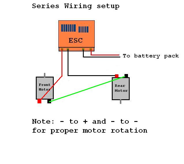
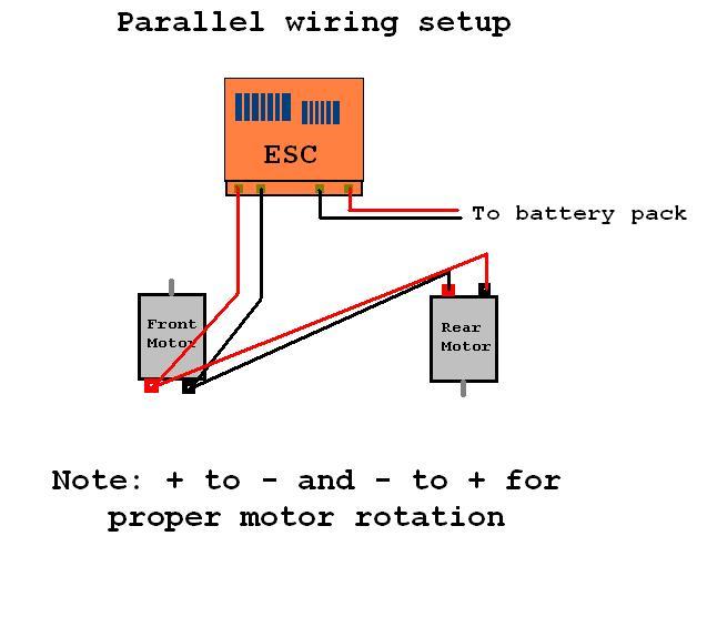
The first step is to decide how you wish to run the motors. They can be ran in parallel or series.
To the best of my knowledge, running in parallel gives approximately a 50% increase in speed, but doubles the load on the ESC.
E.G. two stock motors in parellel puts the same load on the ESC that a single 13-14 turn motor would.
The increased load reduces runtime, but I've found that the Clod gives great runtime to begin with so
that shouldn't be much of a problem.
Running the motors in series puts the load of a single motor of whatever turn motors your running. E.G. two stock motors
in series produces the load of a single stock motor. The series setup does provide better runtime, but at the cost of
performance. If your truck is used solely for rock crawling, the series setup is more than likely what you will want to use
being that speed isnt a top priority.
Step 2
Now that youve decided which wiring setup is for you, we can get down to business :-)
I find its easiest to do the wiring with the motors/ESC out of the truck, so go ahead and take them out
if they arent already.
You should now identify which terminal on the motors are positive and which are negative. Most open endbell motors have
the polarity marked on the endbell, but the closed endbell motors (E.G. the Johnson 540's that come with the Clod Buster)
generally do not.
The easiest way to find out the polarity is to just hook up the motor straight to a power source (E.G. a battery pack)
and see what way the armature spins. When + is connected to + and - to - the motor will spin clockwise (this is refered to as normal rotation).
When + is connected to - and - to + the motor will spin counterclockwise (this is refered to as reverse rotation).
NOTE: the motor should be veiwed from above (or in other words you should be looking at the endbell) when checking rotation.
Once you have identified the polarities, scribe them onto the side of the motor can for easy reference.
Step 3
We will now begin soldering, so get out your soldering iron and get it heated up.
You should now lay out your ESC, wiring, and motors as shown on the diagrams.
Now you will solder all the wires as shown on the diagram for whatever setup you plan to use.
Make sure you pay attention to the motor polarities to avoid having to redo any connections.
Once you have everything soldered up, it would be a good idea to test the ESC/Motors prior to installation in your truck.
Make sure both motors are operating, and make sure they are both spining in the corect directions.
Step 4
Assuming you figured out the wiring ;-) you should now install the pinion gears onto the motor shafts. Mount
the motors to the correct gearbox's. Mount your ESC to your chassis. And finally arange and tie strap all the wires.
Nothing ruins a nice looking truck more than a bunch of wires dangling everywhere, so try to get them all aranged and straped
down neatly. As you can see in the following picture, I have all of my wiring aranged and straped down very neatly.
This not only makes your truck look better, but keeps your wires from possibly getting hung on something and damaged.

|